Lucas Flasher Unit Wiring Diagram
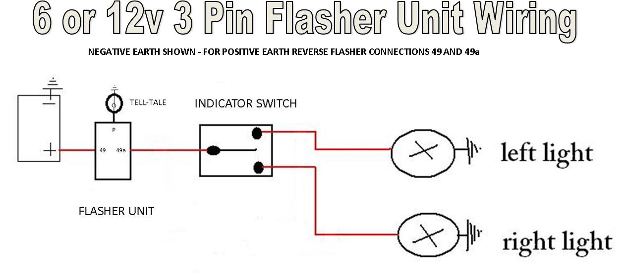
12v only, negative or positive earth. Wiring connections disconnect the battery whilst carrying out any wiring work.

Lucas Flasher Unit Wiring Diagram Wiring View and
Lucas flasher unit wiring diagram.
Lucas flasher unit wiring diagram. The flasher unit clip should be removed from the bracket and used to retain the flasher unit close to the switch. Based on a page by chris kantarjiev of the dimebank garage with several additions and modifications by skye nott. The 2 red wires are connected together and.
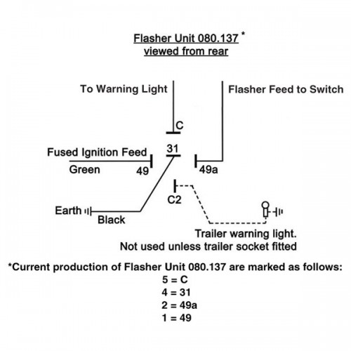
So here are the markings and where they go for a 3 prong flasher unit. This unit needs to be wired in conjunction with a suitable flasher unit and brake light switch. Available from us) and wire it in as per the relay schematic shown in fig 1.
By ania fomicheva on june 04, 2021 in wiring diagram 207 views. You may find it helpful to enlarge the page to 11x17 with a photocopier and trace circuits with coloured pencils. Click on each one to enlarge it.
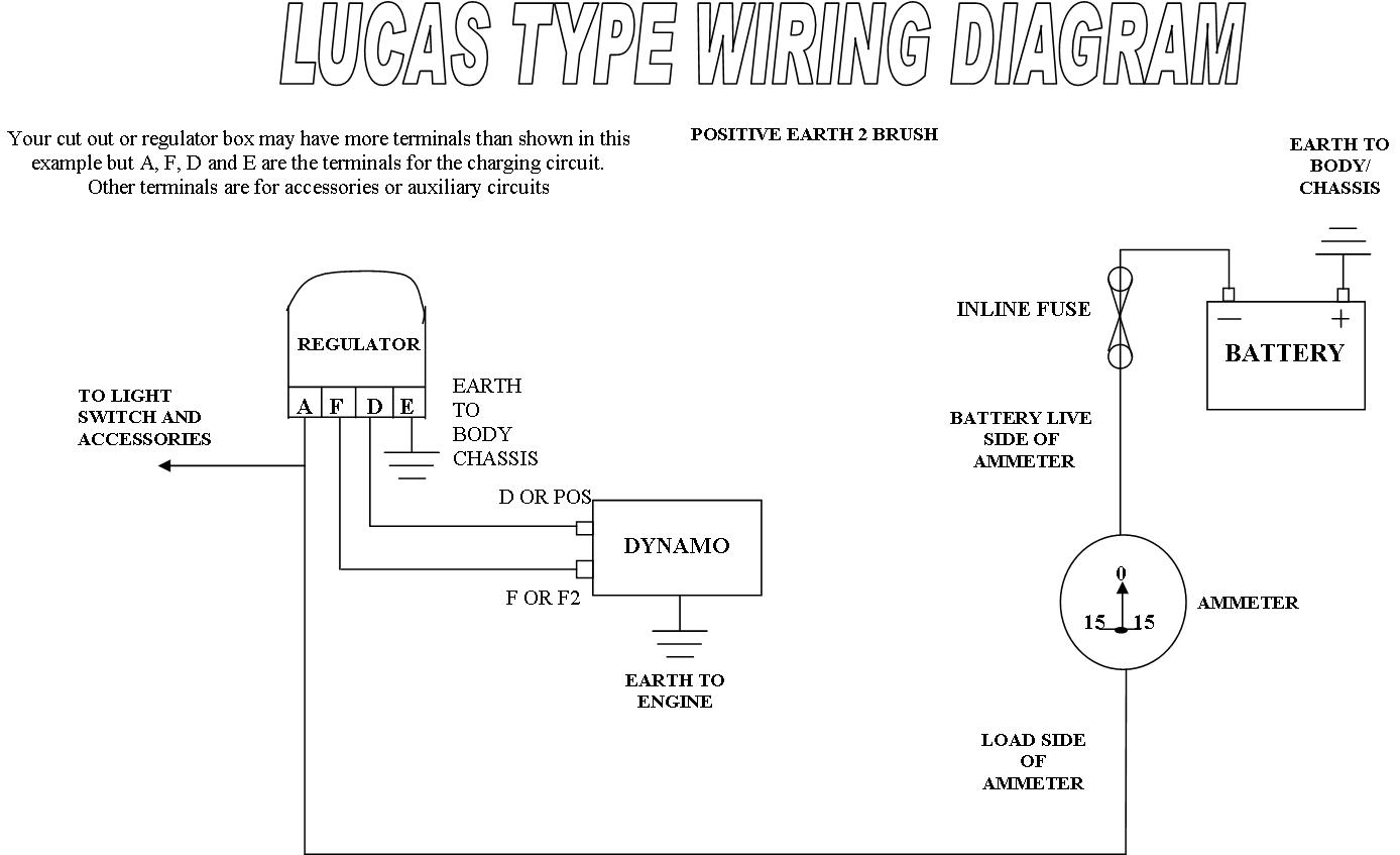
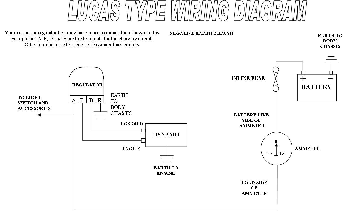
To enable brake lights to be used as rear indicators. Wiring diagrams to help you fit a converted dynamo or regulator or both. Any manual should have a wiring diagram (haynes is fine).
Note that the pin configuration is different on a standard iso relay than on the lucas delay module, fig 2. If not, the structure won't work as it ought to be. Spb120 flasher switch wiring instructions ( as viewed from rear of switch ) r/h.
Lucas flasher wiring diagram written by tuju123 friday, 28 may 2021 add comment edit. With the ignition on, earth the tester and probe the feed wire connector:the lamp should light. Lucas flasher wiring diagram orlando mustang parts inventory serving southeast usa, technical, dynatrak bass boat, morgan electrical gomog, vauxhall cars all bits for old vauxhalls old classic car, motorcycle amp vintage car indicators claranet soho, modern flasher circuits
Use a test lamp to check that power is reaching the flasher unit. Although the flasher units have been known to last for decades, the eventual failure mode will most likely be a broken wire in the heater element. The lucas db10 relay was fitted to a considerable number of british cars in the 50s through to the 70s,.
Use the relevant diagram along with the supplied written instructions to check your wiring and connections during and after installation and. To test the conventional type of flasher unit, use a circuit tester between the terminal marked b on the unit and the earth. Before that happens it may develop a corroded contact for the pilot lamp, thereby disabling the indicator light on.
The same code works for the 2 pin flasher as well. Flasher units have to be connected to the turn signal switch circuit in a certain way and are marked in a way that is far from obvious. The 4 yellow wires are all connected together and to the output from the turn and hazard flasher units.
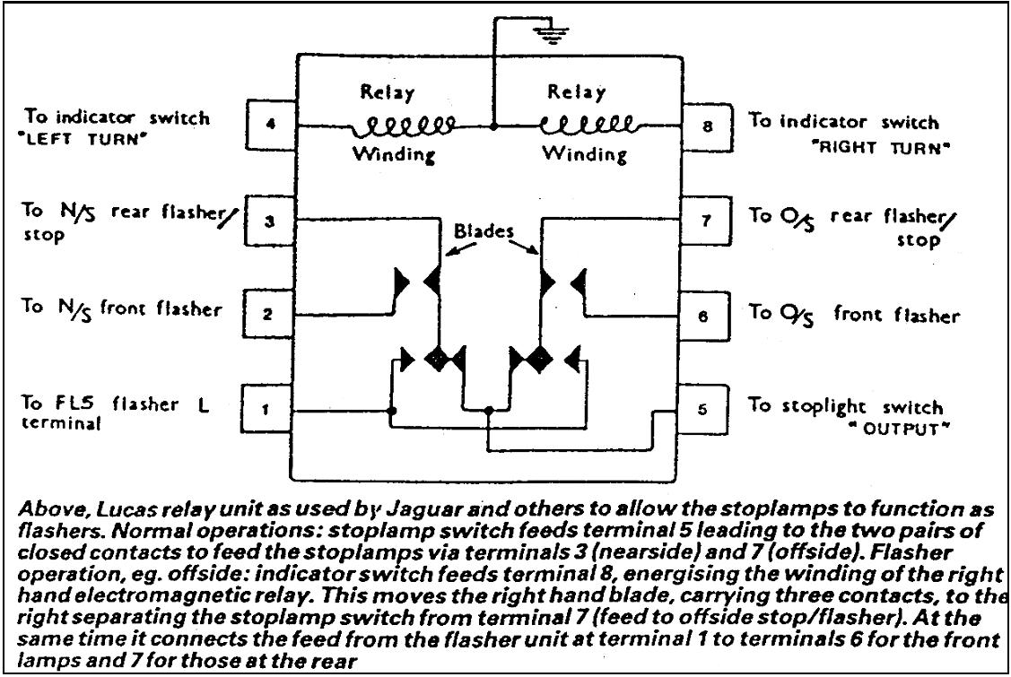
2 pin flasher unit wiring diagram. Fig 2 lucas with iso numbering 30/51 87 87a fig 1 85 86 jaguar xj6 s3 flasher indicators radio, aerial, boot lights 7 Each part should be placed and linked to other parts in specific way.
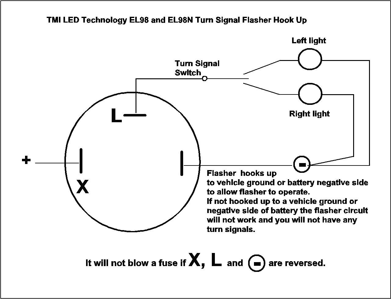
Just an idea on how the old style mechanical thermal flasher works Lucas 33117 or db10 style flasher unit. Connect the purple wire to a suitable 12v permanent live source.
Place the center connector of the test bulb on the battery. At this point, the unit should start flashing, causing both the test light and.

Flasher Unit Wiring Diagram 2 Pin Wiring Diagram

LUCAS SFB161 Flasher Unit

Lucas Flasher Unit Wiring Diagram Wiring Diagram
Lucas Flasher Unit Wiring Diagram Wiring Diagram
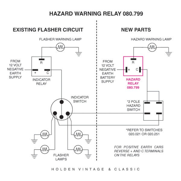
Lucas Relay Wiring Diagram DRAMAPICISAN
to the Austin Seven Friends web site and forum A

Wiring diagrams to assist you with connecting up
2 Pin Flasher Relay Wiring Diagram Wiring Diagram
Wiring Diagrams

Lucas DB10 flasher unit

Wiring Diagram For Lucas 6ra Relay
Lucas Flasher Unit Wiring Diagram Collection
12V Electronic 4 terminal


Durite Flasher Unit Wiring Diagram Wiring Diagram

Wiring Diagram For Flasher Relay
Lucas Flasher Wiring Diagram Wiring Library

New wiring loom install issues Defender Source

Wiring Diagram Info 24 4 Way Flasher Wiring Diagram
Lucas Flasher Unit Wiring Diagram Wiring Diagram